Our Journey for Autodrive F1Tenth Competition - Part 1
- Aman Kumar Singh
- Dec 1, 2024
- 3 min read
Updated: Feb 27, 2025
Competing in the F1TENTH Sim Racing League at IROS 2024 has been an exciting challenge for our team. Using the AutoDRIVE Ecosystem, we set out to develop a high-performance autonomous driving algorithm for a 1:10 scale race car.
The goal? Make the car drive as fast as possible while avoiding collisions—both in qualification and during the final time-attack race on an unseen track.

The Competition Format
The race had two key stages:
Qualification Race – Our first hurdle was to complete 10 clean laps around a practice track without hitting the track boundaries. This tested our car’s reliability and control.
Time-Attack Race – The real challenge came when we were placed on a completely new racetrack. With no prior knowledge of the layout, we had to rely on our algorithm’s adaptability. The fastest lap time determined the winner.
Getting Started: Team Formation and Registration
We took F1TENTH Sim Racing League Competition as our course project for the "AI/ML in Robot Autonomy". The work began in the early weeks of the course when we formed our team and officially registered for the competition. The challenge was clear: develop an autonomous driving algorithm for a 1:10 scale race car that could navigate a racetrack at high speeds while avoiding collisions.
Laying the Foundation: Setting Up Our Simulation Environment
To begin development, we needed a robust simulation setup. We used the AutoDRIVE Simulator, which provided a digital twin of the F1TENTH car and racetrack. Setting up the simulator required installing Docker and NVIDIA-Docker2 before running the necessary containers. This allowed us to test and refine our approach in a controlled, repeatable environment.
Mapping the Racetrack with SLAM
Before we could develop a racing strategy, we needed an accurate map of the racetrack. For this, we used SLAM Toolbox in ROS2, which allowed us to generate a map of the environment while simultaneously localizing our vehicle.
How SLAM Works
SLAM (Simultaneous Localization and Mapping) operates by:
Capturing Sensor Data – The race car continuously scans its surroundings using LIDAR and other onboard sensors.
Building a Map – As the car moves, SLAM incrementally constructs a 2D map, identifying track boundaries, free space, and obstacles.
Localizing the Car – The algorithm estimates the car's position within the map, ensuring it knows its precise location at all times.
To keep our system organized, we structured the TF2 transformation tree in ROS2 as follows:
map → odom → base_footprint → base_link
The map frame represents the entire racetrack.
The odom frame keeps track of local movement.
The base footprint frame defines the car's position on the ground.
The base link frame represents the car's main body.

This transformation hierarchy ensured that all sensor data and movement calculations remained consistent throughout our development process.
Extracting the Racetrack from SLAM Data
Once the map was generated, we needed to extract key racetrack features, such as:
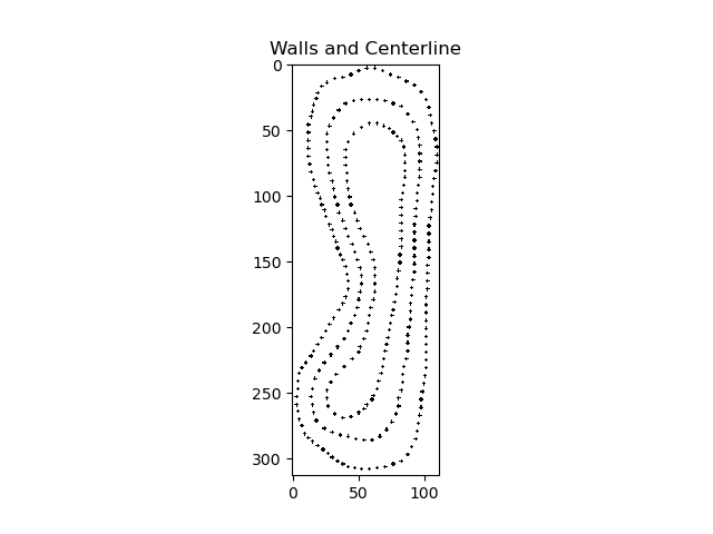
Centerline – The ideal racing line.
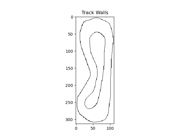
Inner and Outer Boundaries – Defining track limits.
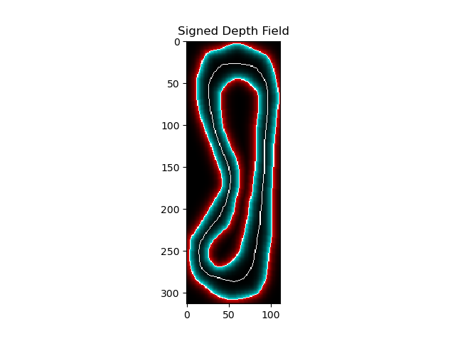
Signed Distance Field – Measuring the distance of any point to the nearest boundary.
Computer Vision Approach
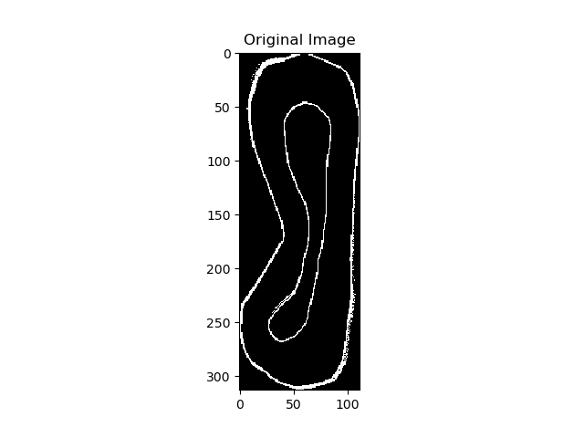
To process the SLAM-generated PGM map file, we used image processing and contour detection techniques:
Preprocessing – We loaded the grayscale map and filtered relevant pixels.
Contour Detection – We identified the track edges and centerline using thresholding and subsampling.
Transforming to Real-World Coordinates – We applied scaling factors from the YAML configuration file to convert pixel positions into meter-based coordinates.
CSV Export – Finally, we exported the processed track data (centerline, boundaries, and signed distance field) into CSV format for further use in trajectory planning.


Next Steps
With the racetrack mapping complete, we’re now focusing on:
Global and Local Planning – Implementing planning algorithms to optimize our car’s racing trajectory.
Trajectory Optimization and Testing – Fine-tuning the planned path for speed and stability.
The initial setup phase laid a solid foundation for the weeks ahead. Stay tuned as we dive deeper into the racing strategy and algorithm development!