Our Journey for Autodrive F1Tenth Competition - Part 2
- Aman Kumar Singh
- Dec 8, 2024
- 3 min read

Updated: Feb 27, 2025
After our initial attempts at generating a raceline, we encountered an issue, our map data was not accurate enough to produce a reliable trajectory. When tested with a standard Pure Pursuit Controller, the car struggled to follow the track.
In this phase of our F1TENTH Sim Racing League journey, we focused on high-resolution mapping and a more precise raceline extraction method to improve trajectory planning. Here’s how we tackled the challenge.
Refining the Mapping Process with Computer Vision
We improved the computer vision pipeline to extracts the racetrack more effectively. Our approach consisted of four key steps:
1. Euclidean Distance Transform (EDT):
We first applied EDT to the map, which calculates the distance of each pixel to the nearest obstacle (e.g., track walls). This gave us a distance field that highlighted navigable areas and provided a strong foundation for raceline extraction.
2. Skeletonization:
Next, we applied skeletonization to convert the track into a one-pixel-wide representation of the centerline. This ensured that we captured the fundamental track structure without distortion.
3. Depth-First Search (DFS) for Ordered Centerline Extraction:
A simple skeleton isn’t enough we needed an ordered sequence of points for smooth path planning. Using Depth-First Search (DFS), we systematically extracted the centerline coordinates.
4. Transforming Pixel Data to Real-World Coordinates:
Once we obtained the centerline, we converted pixel coordinates to real-world meter values using the .yaml file from our mapping process. This step allowed us to align the track with the actual racing environment.
We successfully generated an accurate and smooth raceline that would serve as the foundation for our trajectory optimization.


Velocity Profile Generation for Optimized Trajectory Planning
With an improved raceline in place, we turned our attention to generating an optimized velocity profile. This step ensures that our car drives not just accurately, but also as fast as possible while maintaining stability.
Integrating Velocity Profiles into Controllers
To enhance our control system, we modified the global trajectory generation script to make it compatible with controllers like Stanley, LQR, and Pure Pursuit. This involved:
Defining the Optimization Objective
The goal was to minimize lap time while maintaining stability and feasibility.
Trajectory Optimization Approaches
Shortest Path: Finds the shortest possible racing line.
Minimum Curvature: Ensures smooth turns by minimizing sharp changes.
Iterative Minimum Curvature: Refines the previous approach iteratively.
Minimum Time (Mintime): Uses vehicle dynamics constraints to generate the fastest feasible trajectory.
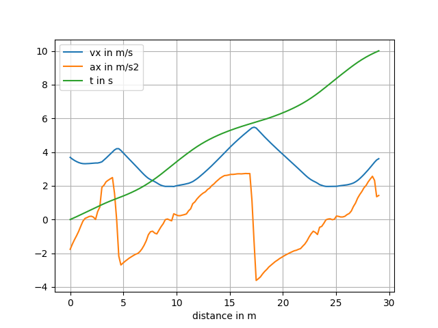
Velocity Profile Calculation
We used GGV diagrams (which model vehicle grip, acceleration, and speed limits) to assign optimal speeds to each segment of the track.
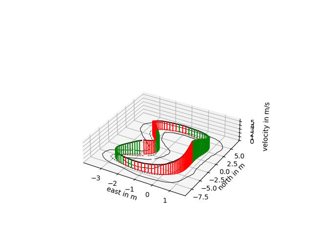
Final Path and Speed Profiles
The velocity profile was fine-tuned to ensure the car doesn’t exceed handling limits while maximizing speed through corners.
Mathematical Formulation of the Optimization Problem
To formalize our approach, we modeled the trajectory optimization as a constrained minimization problem:

Where:
x(t) represents the vehicle state (position, velocity, heading, etc.).
u(t) represents the control inputs (steering, acceleration).
κ(x,α) is the curvature of the path.
v(t) is the velocity profile along the trajectory.
Dynamic constraints ensure that the vehicle stays within feasible limits.
By solving this optimization problem, we obtained an optimal raceline and velocity profile for our controllers.


Testing with Geometric Controllers
With our optimized path and velocity profiles, we proceeded to test the system using geometric controllers, particularly:
Pure Pursuit Controller
We ran tests using our Pure Pursuit node, ensuring that the car followed the optimized path smoothly. Initial results were promising, showing significantly improved tracking performance compared to our earlier attempts.
LQR Problem Formulation
We formulated the vehicle tracking as a linear system:
x_dot=Ax+Bu
x is the state vector (position error, heading error, velocity deviation).
u represents control inputs (steering angle, acceleration).
A and B are system matrices derived from vehicle dynamics.
We then solved for the optimal control law:
u = − K x
where K is the LQR gain matrix, obtained by solving the Riccati equation.
Final Results
After weeks of development and testing, we competed in the F1TENTH Sim Racing League at IROS 2024. Against 58 teams, we secured 5th place, a strong result given the competition's intensity.

Qualification Round
Final Round


Comments